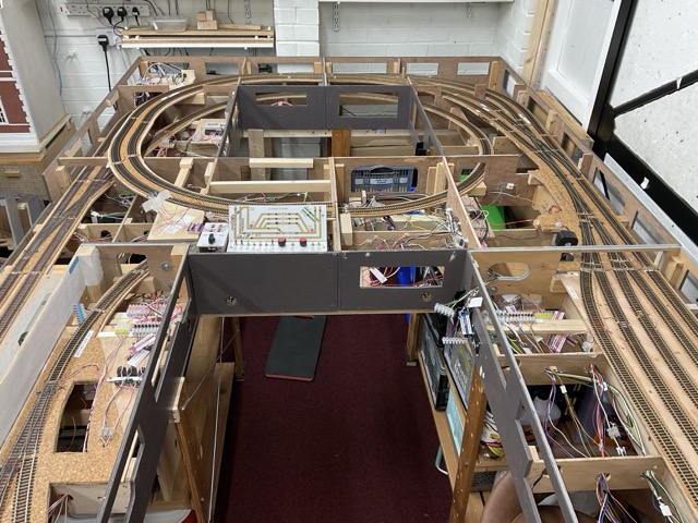
The garage and bases were now ready for the layout and the next shows some of the lower boards in situ, but not joined up. Note the top right board (L2) which would later undergo serious surgery. But the bottom right of that board (on that picture) is where the power sockets were located in Chorley and these fed into the power units (four mains leads). I could have found some solution to leaving them unchanged but I also wanted to tidy up the wiring which was a mess as the layout had evolved beyond the initial plans. So, I decided to have all the wires coming in at the top left of the picture and where necessary redo the wiring and tidy it up at the same time.
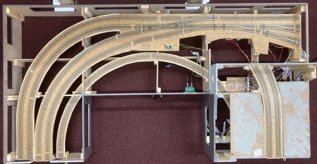
The top of Board 2L mentioned above. The arrangement of points and a diamond crossing ought to be fairly simple but I had designed it such that on the left the outer, main line, was falling to the left and the inner double is the spiral, rising from the same point and the track to the right is also rising. The double track on the bottom right is a continuation of the spiral which joins to lower board 1 below and upper board 2 above. This latter join from 2L to 2U was a constant source of trouble as the join is on an angle. After the move I found it difficult to get the alignment. The problems of the diamond and the spiral join led later to the decision to split this board in two and rework the track. At the time of writing (August 2025) I think these problems have been solved but where there is a problem on this board, hidden beneath the upper layer, finding and accessing the trains is hard.
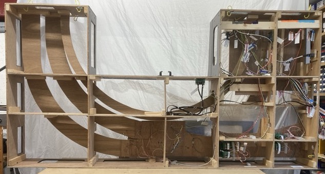
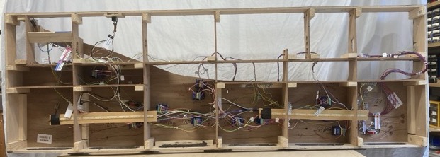
The underside of board 2L. In Chorley a cluster of wires rose up from the power units situated on the supports just under what is the bottom right of the picture. Some of those wires went to the track and point-work on this board but many more went to board 3L on the right, and board 1L at the top right.
Upper Board 3 is also shown below - the track layout first and then the wiring underneath. All the track had been wired but only a few signals were in place. There are locations for two uncouplers and the Upper Panel which has a lot of wires going to other boards.
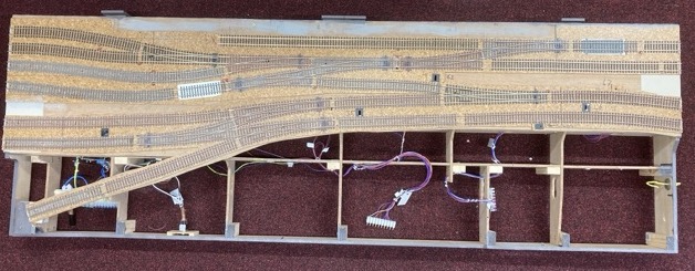
Board 3U competes with 1L and 2L for the most complicated wiring, and this was when more was to be added. Also shows is two strips of LEDs for the under-board wiring.
To be continued… with a page about the power units, panels, wiring and accessories before moving on to the current state.